A breaker box, also known as an electrical panel, load center, or service panel, serves as the central distribution point for electricity within a building. It receives main power from the utility and distributes it to individual circuits, while providing crucial protection against overloads and short circuits through circuit breakers.
Key Components in a Breaker Box Diagram
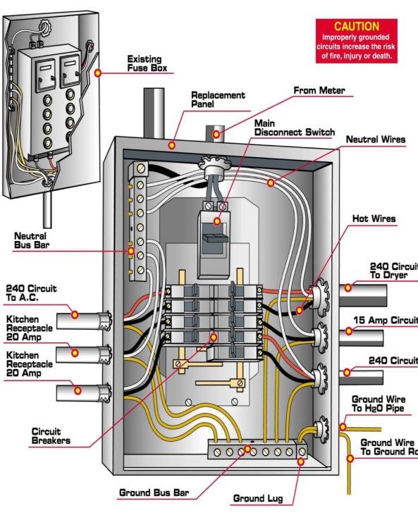
Understanding a breaker box diagram involves recognizing its fundamental components and their arrangement:
- Main Breaker: This is typically the largest breaker, usually located at the top or sometimes at the side of the panel. It acts as the master switch, controlling all power to the circuits connected to the panel. Turning off the main breaker disconnects power to all branch circuits, but the lugs (terminals) where the utility service wires connect to the main breaker remain live.
- Hot Bus Bars: These are usually two thick metal bars (typically copper or aluminum) that run vertically behind the circuit breakers. They receive power from the main breaker (or main lugs in panels without a single main breaker) and distribute it to the individual circuit breakers. In a standard North American residential panel, each bus bar carries 120 volts to neutral, providing 240 volts between them.
- Circuit Breakers (Branch Breakers): These are individual protective devices designed to interrupt the flow of electricity to a specific circuit if an overcurrent (overload) or short circuit occurs. They snap onto the hot bus bars and have terminals for connecting the hot wire(s) of the branch circuit. They come in various amperage ratings (e.g., 15A, 20A, 30A) and types (e.g., single-pole, double-pole, AFCI, GFCI).
- Neutral Bus Bar: This is a conductive metal bar with multiple screw terminals where all the white insulated (neutral) wires from the individual branch circuits are connected. It provides the return path for current under normal operating conditions. In main service panels, the neutral bus bar is bonded (connected) to the panel enclosure and the grounding system.
- Grounding Bus Bar: This is another conductive metal bar with screw terminals for connecting all the bare copper or green insulated (ground) wires from the branch circuits, as well as the grounding electrode conductor (which connects to earth). It provides a safe path for fault current to flow to the ground, minimizing electrical shock hazards. In main panels, it is typically bonded to the neutral bus bar. In subpanels, the ground and neutral bars must be kept separate.
- Service Entrance Conductors: These are the large wires that bring electrical power from the utility meter into the main lugs of the panel, or directly to the main breaker. They typically consist of two hot conductors and one neutral conductor.
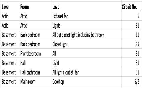
- Panel Directory/Schedule: A label or chart, often located on the inside of the panel door, that lists each circuit breaker and the area or appliances it serves. A clear and accurate directory is essential for identifying circuits quickly and safely.
Interpreting a Diagram
A breaker box diagram visually represents the electrical connections within the panel. Lines indicate wires, showing how power flows from the service entrance conductors, through the main breaker, to the hot bus bars, and then through individual circuit breakers to the branch circuits. The diagram also illustrates the connections of neutral and ground wires to their respective bus bars. Symbols are used to denote breakers, bus bars, and connection points.
Safety Considerations
Working inside a breaker box can be extremely dangerous due to the risk of electric shock, arc flash, and fire. Such work should only be performed by qualified and licensed electricians. Even if the main breaker is turned off, the service entrance conductors and the lugs they connect to remain energized unless the power is disconnected at the utility meter. Always assume all components inside an electrical panel are live until verified otherwise with appropriate testing equipment by a qualified professional.