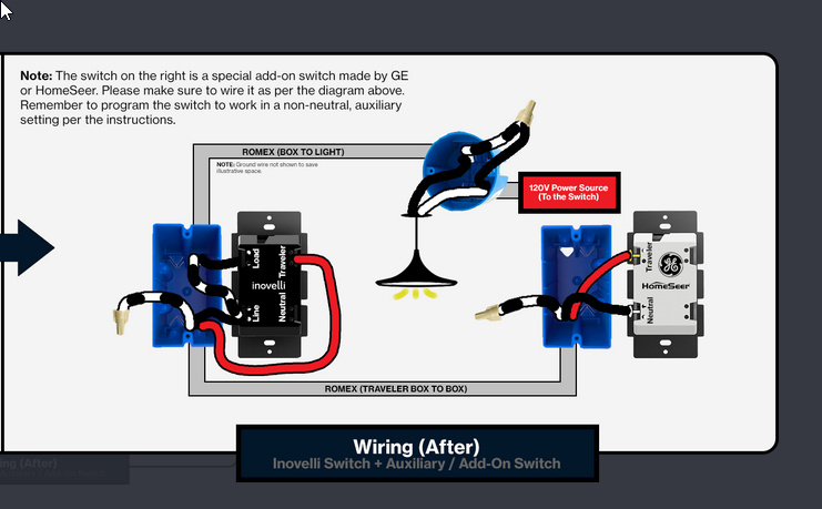
Understanding Three-Way Switches
A three-way switch system enables control of a single light fixture or electrical outlet from two distinct locations. This setup requires two specialized three-way switches and appropriate electrical wiring.
Key Components and Terminals
Before commencing any wiring, familiarize yourself with the essential components:
- Three-Way Switches (x2): These switches differ from standard single-pole switches as they feature three screw terminals (excluding the ground screw).
- Common (COM): This terminal is typically distinguished by a darker color (black or bronze). It serves as the pivot for the switching mechanism. The "hot" wire from the power source or the wire leading to the load (light fixture) connects to this terminal.
- Traveler Terminals (x2): These are usually lighter-colored screws (brass). Wires known as "travelers" connect these terminals between the two switches, facilitating the transfer of power.
- Ground Terminal: A green screw designated for the ground wire connection.
- Electrical Cable: For connections between the two switches, a 3-conductor cable (e.g., 14/3 NM-B or 12/3 NM-B, depending on circuit amperage) is commonly used. This cable typically contains a black wire, a red wire (often used as travelers), a white wire (neutral), and a bare copper ground wire. A 2-conductor cable (e.g., 14/2 or 12/2) is used for the power feed to the first switch and from the second switch to the light fixture.
Common Wiring Method: Power to Switch Box 1, then to Switch Box 2, then to Light Fixture
This is a widely used configuration for three-way switch installations. The following steps detail this method:
SAFETY FIRST: Always disconnect power at the main circuit breaker or fuse box before undertaking any electrical work. Confirm that the power is off using a non-contact voltage tester at the work area.
Wiring at Switch Box 1 (Power Source Entry)
- Incoming Power Cable (2-conductor from source):
- Connect the black (hot) wire from the power source to the Common (dark-colored) terminal on the first three-way switch.
- Connect the white (neutral) wire from the power source to the white (neutral) wire of the 3-conductor cable that runs to Switch Box 2. Use a wire connector for this splice. This neutral wire bypasses the switch mechanism.
- 3-Conductor Cable (to Switch Box 2):
- Connect the black wire from this cable to one of the traveler (light-colored) terminals on Switch 1.
- Connect the red wire from this cable to the other traveler (light-colored) terminal on Switch 1.
- The white (neutral) wire from this cable is already connected to the incoming source neutral.
- Ground Wires:
- Connect all ground wires (from the source cable, the 3-conductor cable, and a short pigtail wire if needed) together with a wire connector. Attach the pigtail to the green ground terminal on Switch 1.
Wiring at Switch Box 2 (Leading to Light Fixture)
- 3-Conductor Cable (from Switch Box 1):
- Connect the black (traveler) wire from this cable to one of the traveler (light-colored) terminals on Switch 2.
- Connect the red (traveler) wire from this cable to the other traveler (light-colored) terminal on Switch 2. (The order of connection for the two traveler wires on the traveler terminals does not matter, as long as they are indeed the traveler wires.)
- Cable to Light Fixture (2-conductor):
- Connect the black wire (this will carry the switched hot to the light) from this cable to the Common (dark-colored) terminal on Switch 2.
- Connect the white (neutral) wire from this cable to the white (neutral) wire arriving from Switch Box 1 (via the 3-conductor cable). Use a wire connector.
- Ground Wires:
- Connect all ground wires (from the 3-conductor cable, the cable to the light fixture, and a pigtail if needed) together. Attach the pigtail to the green ground terminal on Switch 2.
Wiring at the Light Fixture
- Connect the black (switched hot) wire coming from the Common terminal of Switch 2 to the hot (usually brass or black) terminal on the light fixture.
- Connect the white (neutral) wire (which originates from the power source and has been passed through the switch boxes) to the neutral (usually silver or white) terminal on the light fixture.
- Connect the bare copper or green ground wire to the light fixture's ground screw or wire.
Final Steps and Testing
- Carefully fold all wires into their respective electrical boxes, ensuring no bare conductors are exposed or pinched.
- Securely mount the switches into their boxes and attach the light fixture.
- Install switch cover plates and the light fixture canopy or cover.
- Restore power at the circuit breaker.
- Test the operation. The light should turn on or off from either switch location, regardless of the position of the other switch.
Disclaimer: Working with electricity can be hazardous. If you are uncertain about any aspect of this wiring process or uncomfortable performing the work, consult a qualified licensed electrician. Always adhere to all applicable local electrical codes and safety regulations.


