A 3-way dimmer switch circuit enables control and dimming of a single light fixture from two distinct locations. Typically, this setup involves one dimmer switch and one standard 3-way switch.
Wire Identification
Before proceeding with any wiring, ensure the circuit breaker supplying power to the switches is turned OFF.
- Hot (Line/Power In): The wire supplying power from the electrical panel, usually black.
- Load (To Light): The wire carrying power from the switches to the light fixture, often black.
- Travelers: Two wires that connect between the two switch locations. These are commonly found in a 3-wire cable (e.g., black and red wires, with the white wire being neutral and a bare copper/green for ground). Their color can vary, so proper identification is key.
- Neutral: The wire (typically white) that completes the circuit. While not always directly connected to basic switches, it is usually present in the switch boxes and is often required for smart dimmers.
- Ground: The safety wire, usually bare copper or green insulated.
Switch Terminal Identification
- Common (COM) Terminal: This screw terminal is usually a different color (e.g., black or dark bronze) from the others. The Hot wire connects to the Common terminal on the switch where power enters the 3-way circuit. The Load wire to the light fixture connects to the Common terminal on the other switch.
- Traveler Terminals: Two screw terminals (often lighter brass or silver) for connecting the traveler wires.
- Ground Terminal: A green screw for the ground wire connection.
Wiring Configuration Example
This common configuration assumes power feeds into the first switch box (where the dimmer will be installed), and the light fixture is fed from the second switch box (with a standard 3-way switch).
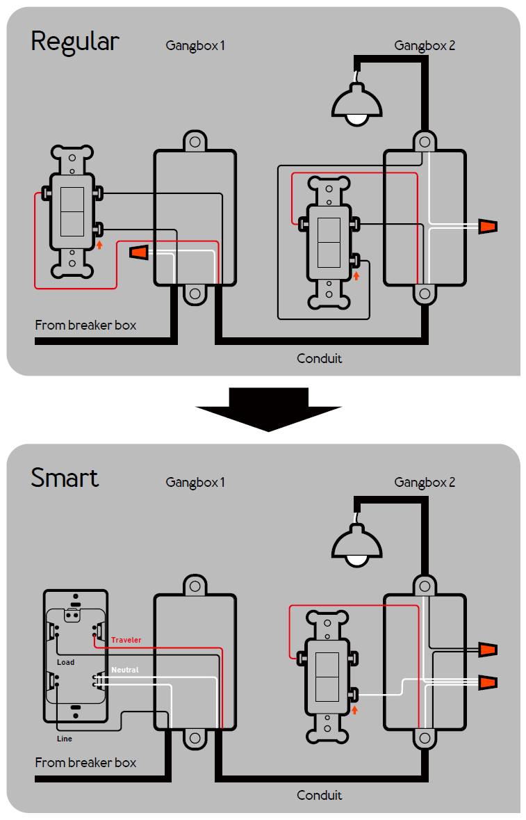
Switch Box 1: Dimmer Switch Installation
- Connect the Hot (Line/Power In) wire to the Common (COM) terminal on the dimmer switch.
- Connect the two Traveler wires (that go to Switch Box 2) to the two Traveler terminals on the dimmer switch. The specific terminal for each traveler usually does not matter, but consistency is good practice.
- Connect the Ground wire to the green ground screw on the dimmer.
- If the dimmer switch requires a neutral connection (common for smart dimmers), connect its neutral pigtail to the bundle of neutral (white) wires in the box using a wire connector. If not required, ensure existing neutral wires remain securely connected.
Switch Box 2: Standard 3-Way Switch Installation
- Connect the two Traveler wires (coming from the dimmer switch in Switch Box 1) to the two Traveler terminals on the standard 3-way switch.
- Connect the Load wire (that goes to the light fixture) to the Common (COM) terminal on the standard 3-way switch.
- Connect the Ground wire to the green ground screw on the switch.
- Ensure all neutral (white) wires in this box are securely connected together with a wire connector.
Critical Notes
- Safety First: Always de-energize the circuit by turning off the breaker before starting any electrical work. If you are uncertain about any step, consult a qualified electrician.
- Single Dimmer Usage: In a standard 3-way circuit, only one dimmer should be used. Installing two standard dimmers can cause malfunction or damage. Special multi-location dimming systems exist but have specific wiring requirements.
- Neutral for Smart Dimmers: Many smart dimmers require a neutral wire for operation. Verify the dimmer's requirements and ensure a neutral wire is available in the switch box.
- Grounding: Always connect all ground wires to the switches and to each other for safety.
- Pre-existing Wiring: If replacing old switches, carefully label the wire connected to the common (darker screw) terminal before disconnecting it. This is crucial for correct re-wiring.